成都华诚微电子有限公司
Fidelics Microelectronic (Chengdu) Co.,Ltd.
http://www.fidelics.com
Thin Film MIS Chip Capacitor
Description:Thin film MIS(Metal-Insulator-Semiconductor)chip capacitors use high density and high quality SiO2 and/or Si3N4 thin film(100-400nm)grown on Si wafers with high conductivity, and are manufactured by thin film process techniques. They feature good quality and performance with small size, high Q value, low insertion loss, and good temperature stability characteristics ideally suited for Microwave Integrated Circuits (MICs) up to 40GHz 。
With 3μm Au on the front side pad they are excellent for wire bonding, and with back side Au they are also good for Au-Tin, Au-Ge and conducting epoxy die attach. Further design in recessed metallization on the front pad can minimize the potential for shorting during die-attach and wire-bonding。
We offer both Single-pad and Multi-pad capacitors。Single-pad capacitors are mainly used for DC blocking, RF bypass, source bypass, filtering, and impedance matching, and Multi-pad capacitors are mainly used for matching networks, Tank circuits, and dielectric resonator tuning and coupling。
Features:Good quality and performance with small size, high Q value, low insertion loss, and good temperature stability characteristics;recessed metallization minimizing the potential for shorting during die-attach and wire-bonding;good solder-ability and wire-bonding;low temperature coefficient: 50ppm/oC; operating temperature: -55℃ - +200℃。
Product Part Number (P/N) Information:
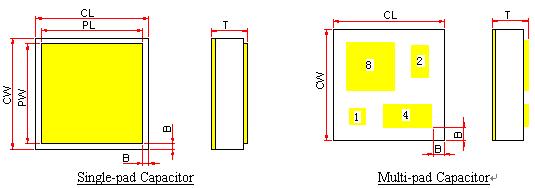
Thin Film MIS Chip Capacitor Drawings:
Product Series:
|
P/N |
CW & CL
Cap. Size
(inch) |
PW & PL
Pad Size
(inch) |
T
Thickness
(inch) |
Capacitance
(pF) |
Rated
Voltage*
VR(Vdc) |
|
FCS-3232-05-200 |
0.032 |
0.028 |
0.005 |
200 |
25 |
|
FCS-3232-05-150 |
0.032 |
0.028 |
0.005 |
150 |
25 |
|
FCS-3232-05-100 |
0.032 |
0.028 |
0.005 |
100 |
50 |
|
FCS-1818-05-050 |
0.018 |
0.014 |
0.005 |
50 |
25 |
|
FCS-1818-05-025 |
0.018 |
0.014 |
0.005 |
25 |
50 |
|
FCS-1010-05-010 |
0.010 |
0.006 |
0.005 |
10 |
25 |
|
FCS-1010-05-005 |
0.010 |
0.006 |
0.005 |
5 |
50 |
|
FCS-1010-05-004 |
0.010 |
0.006 |
0.005 |
4 |
25 |
|
FCS-1010-05-003 |
0.010 |
0.006 |
0.005 |
3 |
25 |
|
FCS-1010-05-002 |
0.010 |
0.006 |
0.005 |
2 |
50 |
|
FCS-1010-05-001 |
0.010 |
0.006 |
0.005 |
1 |
125 |
|
FCS-1818-05-1/2/4/8 |
0.018 |
Per Drawing |
0.005 |
1、2、4、8 |
50 |
|
FCS-1818-05-0.5/1/2/4 |
0.018 |
Per Drawing |
0.005 |
0.5、1、2、4 |
125 |
Note:*:Dielectric Withstanding Voltage (DWV) tested at 2.5* VR。
“B”: Recessed Metallization width typically larger than 0.002 inch。
Low insertion loss:typically less than 0.1dB at 10GHz。
Length (L) and Width (W) Tolerance:±0.002”;
Thickness (T) Tolerance:±0.001”;
Capacitance Variation:typical ±10% ; ±5% also available。
Dielectric Properties (Ta=25℃):
|
Relative Dielectric Constant @1MHz |
Temperature Coefficient(ppm/℃) |
Dissipation Factor
@1MHz(Max. %) |
Insulation Resistance
(GΩ) |
|
3.9 |
50 |
0.1 |
>1000 |
|